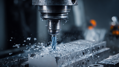
How to Choose an Industrial CNC Milling Machine in 2026?
Choosing an industrial CNC milling machine in 2026 means matching real production needs to measurable machine capabilities. A larger work envelope may look attractive, but it can add cost without improving the parts you make. Start with material, part dimensions, tolerances, and expected output. An aluminum housing and a hardened-steel component place different demands on spindle power, rigidity, tooling, and coolant.
Consider whether a three-axis machine can handle your parts, or whether five-axis movement would reduce setups and improve access to angled features. Check spindle speed and torque, tool-changer capacity, chip evacuation, probing options, and control compatibility. Details matter. A machine’s advertised accuracy is only one part of the decision; the result also depends on workholding, tooling, maintenance, and operating conditions. No specification sheet tells the whole story.
This guide explains how to compare machine configurations, estimate total ownership costs, and assess supplier support in 2026. Ask for evidence that fits your work: documented specifications, sample cuts using representative materials, and clear service and training plans. If possible, review references from shops producing similar parts. A showroom demonstration can be useful, but it may not reflect your daily cycle times or changeovers. Be cautious about choosing by price or headline performance alone. Even a well-matched machine can disappoint when installation, operator training, or maintenance planning is overlooked. The right choice is not always obvious, and some trade-offs remain; careful evaluation makes them easier to see before purchase.
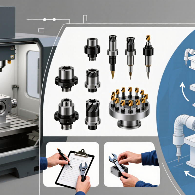
Define Part Geometry and Choose Between 3-, 4-, and 5-Axis Milling
Start with the part, not the machine. Mark every machined face, angled feature, hole pattern, and tight tolerance on the drawing. A flat plate with features on one side may suit a 3-axis mill. It is often simpler to fixture, program, and inspect. That matters when repeatability and setup time drive production.
Add a rotary axis when the part needs machining around a cylinder or on several indexed sides. A 4-axis setup can cut those features without repeated manual repositioning. Fewer setups can reduce alignment errors. But rotary fixtures take space, and long or flexible parts may still vibrate. Check tool access and clamping before assuming the extra axis will help.
A 5-axis mill can tilt the tool toward curved surfaces, deep pockets, and compound angles. This may shorten tools and improve surface quality, though programming and collision checks become more demanding. More capability is not always better. Compare cycle time, fixture complexity, operator skills, and inspection needs against the part’s actual geometry. I would verify access with a toolpath simulation, then review the result at the machine; simulations do not catch every practical nuisance. A small test cut can reveal chatter or awkward chip removal.
Match Spindle Speed and Torque to Material and Cutting-Tool Requirements
Spindle speed and torque should match the material, cutter diameter, and cut depth—not just the machine’s maximum rpm. ASM Handbook, Volume 16: Machining, provides cutting-speed data by workpiece and tool material, but those values are starting points, not guarantees. For example, a 10 mm cutter at an illustrative 120 m/min requires about 3,820 rpm, using n = 1,000 × cutting speed ÷ (π × cutter diameter). Check the tool maker’s range and the machine’s power curve before setting the program. Numbers matter.
Torque becomes critical when the cut is heavy or the spindle runs slowly. A machine may advertise high peak torque, yet provide less continuous torque at the rpm your cutter needs. Use P(kW) = torque(N·m) × rpm ÷ 9,550 to compare usable power at the cutting point. For aluminum with a small cutter, speed may matter more; for a large cutter in steel, low-speed torque can matter more. It depends on engagement, too. A practical test is to machine the intended material with the actual tool, then inspect for chatter, edge wear, and finish variation. One overlooked detail: a rigid setup can outperform a higher-rated spindle. But it will not rescue a poor speed match.
How to Choose an Industrial CNC Milling Machine in 2026? - Match Spindle Speed and Torque to Material and Cutting-Tool Requirements
Use these indicative planning ranges to compare spindle capabilities. Cutting speeds are approximate starting points for solid-carbide end mills and a 12 mm cutter; actual settings depend on tool geometry, coating, workpiece condition, cut engagement, coolant, and the toolmaker’s recommendations.
| Workpiece material |
Typical carbide cutting speed |
Approx. spindle speed
12 mm cutter |
Torque demand |
Spindle and machine priorities |
Tool and cutting considerations |
| Aluminum alloys |
600–1,200 SFM
(183–366 m/min) |
About 4,900–9,700 rpm |
Low to moderate for many cuts; higher torque helps with large engagement or roughing. |
Favor a high maximum speed, adequate power at higher rpm, and effective chip evacuation. |
Use sharp, polished, aluminum-appropriate flutes. Avoid chip recutting; consider air blast or suitable coolant. |
| Mild and medium-carbon steel |
300–600 SFM
(91–183 m/min) |
About 2,400–4,900 rpm |
Moderate to high, especially for roughing and larger radial engagement. |
Look for useful torque in the mid-speed range, stable power delivery, and a rigid machine structure. |
Choose a steel-rated carbide grade and suitable flute count; maintain a consistent chip load and secure workholding. |
| Stainless steel |
150–400 SFM
(46–122 m/min) |
About 1,200–3,200 rpm |
High; stable torque and rigidity are important under sustained cutting loads. |
Prioritize torque at lower-to-mid rpm, low vibration, and reliable coolant delivery. |
Use a tool grade and geometry intended for stainless steel. Avoid rubbing and dwelling, which can promote work hardening. |
| Titanium alloys |
100–250 SFM
(30–76 m/min) |
About 800–2,000 rpm |
High relative to cutting speed; prioritize torque at low rpm and a rigid tool-workholding setup. |
A strong low-speed torque curve, dependable thermal management, and controlled cutting engagement are valuable. |
Use titanium-appropriate carbide tooling and consistent feed. Avoid prolonged tool contact and excessive heat buildup. |
| Gray cast iron |
200–500 SFM
(61–152 m/min) |
About 1,600–4,000 rpm |
Moderate to high, depending on stock allowance and interrupted-cut severity. |
Favor a rigid spindle and enclosure, stable power, and effective management of abrasive dust and chips. |
Select tooling suited to cast iron and the intended dry or coolant-assisted process; protect machine ways from abrasive fines. |
| Hardened steel |
100–250 SFM
(30–76 m/min) |
About 800–2,000 rpm |
High cutting forces may occur; prioritize rigidity, torque stability, and low runout. |
Choose a rigid machine and spindle system capable of stable operation at the required lower speeds. |
Use tooling specifically rated for the workpiece hardness. Limit tool overhang and follow the toolmaker’s engagement guidance. |
How to compare torque and power:
Spindle torque depends on both power and rpm: torque (N·m) ≈ 9,550 × power (kW) ÷ speed (rpm). For example, 15 kW at 3,000 rpm corresponds to about 48 N·m, while 18 kW at 10,000 rpm corresponds to about 17 N·m. Compare the manufacturer’s spindle power-and-torque curve at your actual cutting speed; maximum rpm or peak power alone does not describe cutting capability.
Selection note: The speed conversions assume a 12 mm cutter and use the standard relationship between surface speed, cutter diameter, and rpm. Treat the figures as starting ranges, not universal feeds and speeds; verify them against the specific toolmaker’s data and conduct a controlled test cut.
Verify Positioning Accuracy Using ISO 230-2 Test Data
How to Choose an Industrial CNC Milling Machine in 2026?
Verify Positioning Accuracy Using ISO 230-2 Test Data
A positioning-accuracy claim needs test data behind it. Ask for the machine’s ISO 230-2 test report, not just a specification sheet. The standard describes methods for measuring positioning accuracy and repeatability along machine-tool axes. Check whether results cover the usable travel, and review both forward and reverse movements. Bidirectional results can reveal backlash or alignment issues that a single-direction figure may miss. Numbers need context. Confirm the test conditions, including temperature, warm-up, measurement setup, and stated uncertainty. A report from a carefully controlled test may not predict performance in your shop without adjustment.
Tips: Match the report to the machine’s configuration and axis travel. Check the measured positioning deviation and repeatability for each relevant axis. Ask when the test was performed and whether the machine has since been moved or serviced. Keep the report for comparison during acceptance checks.
A practical review should connect the figures to your work. For example, a part with close-tolerance holes across a long axis may be sensitive to accumulated positioning error. Compare test results with your process requirements, then discuss any gap with the supplier. Do not treat one favorable value as a guarantee. Cutting forces, temperature changes, tooling, and maintenance can affect actual results. A tidy report is useful, but it is not the whole story. I would also ask how the machine is verified after installation; this step is easy to overlook.
How to Choose an Industrial CNC Milling Machine in 2026: Verify Positioning Accuracy Using ISO 230-2 Test Data
How to read this: The grouped bars show mean positioning deviation in micrometers for forward and reverse approaches at each commanded axis position. Smaller deviations and a smaller gap between directions generally indicate more consistent positioning. This is an illustrative dataset, not a measurement from a specific machine or an ISO 230-2 test report; machine acceptance should use calibrated equipment, repeated bidirectional measurements, and the complete ISO 230-2 evaluation.
Compare Tool-Changer Capacity, Cycle Time, and Production Volume
How to Choose an Industrial CNC Milling Machine in 2026?
Tool-changer capacity should match the parts you actually run, not an impressive number on a brochure. List every cutter, drill, probe, and spare tool needed for a typical job. A 40-tool magazine may suit repeat production, while frequent part changes can make a larger capacity valuable. Still, unused pockets do not increase output.
Cycle time needs a realistic test. Ask for a timed run using your material, toolpaths, and finishing requirements. Include tool changes, probing, workpiece loading, and chip clearing; a fast cutting time can hide slower machine stops. That matters. Record several cycles, since one unusually smooth run may not reflect daily production. Also check whether the machine can keep the spindle cutting while an operator prepares the next part.
Estimate production volume by shift, week, and expected product mix. High-volume work may justify quicker tool changes and automated loading, while smaller batches often benefit more from flexible setups. Compare the machine’s practical cycle time with demand, then leave room for maintenance and occasional delays. A spreadsheet helps, but its assumptions can be wrong. Review them with operators who know the real setup time and common interruptions.
Check Machine Safety Against ISO 16090-1 and Local Regulations
When comparing an industrial CNC milling machine in 2026, treat safety as a purchasing criterion, not a box to tick. ISO 16090-1 covers safety requirements for milling machines and related machining centres. It addresses hazards such as moving axes, rotating tools, ejected chips, and access to danger zones. Ask for the machine’s risk assessment and check that guards, doors, and interlocks suit its intended configuration. Look at emergency-stop locations near the operator and service areas. Small details matter.
Tips: Ask which conformity documents apply in your region, and request the safety manual before purchase. During a demonstration, check that opening an access door stops hazardous motion as intended. Observe how operators clear chips and reach the work area. A checklist helps, but it cannot replace a careful walkthrough.
Local regulations may add requirements for installation, electrical systems, noise, or operator training. Confirm responsibilities with a qualified safety professional and the relevant local authority; requirements vary by location and machine setup. Check that instructions are available in a language operators understand. Paperwork may look complete while a guard is awkward to use, so assess the machine in realistic working conditions. That part is easy to overlook.